ICEngineering Subjects

Monday, February 11, 2013

Two-Strokes and Electrics


Last kart day of the year, Oct 27 2012!

I'm finally getting around to rebuilding the kart, which has been a spectacular autocross and level-1 fun (fun the whole time) success.  The thing's a blast and a workout - driving it helps slow down the other racing, and the physical requirements helps motivate to get stronger.  True, I haven't gone wheel-to-wheel in the kart yet, so I'm certainly no real karter...

My kart reflects that a little.  I got it used, great deal, great working condition, but it's well-worn.  The frame is Trackmagic, a brand known for it's complete lack of support with some odd-sized parts (need to machine a new lower steering column spacer for next season...), and has mismatched knuckles, some welding on it, etc.  The engine fires on the first couple compressions but the inside of it was otherwise a mystery on purchase. 

So rebuilding the engine was interesting, it was the first time I'd seen what modifications are done to it.  The answer is not many...the ports are smoothed, but stock shape and size, transfers are all stock, compression is stock.

As usual, first step is turning working things into piles of gears
Look at all the 2strokes...
Tray 1 of 2. So many parts for such a simple engine!

What's most interesting is the damage found, there's been some fairly impressive detonation history.

Interesting piston damage

I'm still learning what is normal and what is not for this kind of engine and use.  For instance, in the head, I think the damage below is actually normal-ish for extended use!  Comparing the detonation on the head to the piston, I actually think the piston has been swapped after most of that head damage was done, but the previous owner just kept using the old head... let me know if you think otherwise.

Detonation never looked so evenly distributed
Also detonation around top of cylinder, apparently normal (and some lower in the cylinder?...strange)

I ordered a new piston (fancy Wiseco GP, forged) with rings, and I have a new head...that's it for the cranktrain!  It'll go back together with the old cylinder, and the bottom end is good.  Looking for a stock ignition now to get rid of some ballast, and maybe will increase compression ratio by machining the cylinder in the summer if I'm feeling comfortable.  Only thing keeping the kart engine from reassembly is some transmission small parts still on order...about $100 worth of tiny overpriced washers and bushing which I had damaged the first time I ran the kart...without trans fluid...

I'm slapping it back together because again, the purpose of this thing isn't top-level karting, still just practice and experience.  I'd decided to keep this kart and engine going until 4-strokes were legal (expecting 1-2 more years for autocross) and then go in for some nicer stuff.  I am looking forward to racing a kart with less oil burning and noxious pollution.  It would be nice for my interests in car racing and mountain biking to be less opposed, not to mention becoming less of a giant tool who selfishly contributes to ruining the world by purposely running unbelievably polluting things for fun...


However, now I don't think I'll ever go 4stroke.  I think my next kart will be electric. (And yes, I am concerned about battery manufacturing and disposal, jury is still out)

The 86g soft LiPo battery in this costs $7 and is rated to 30amps at 8.4V!  Battery technology is truly improving

After taking custody of one of Kenneth's older RC cars needing only a once-over and a battery, I have been impressed by the capability now so easily available.  The above battery is essentially rated to 1/3 hp, costs $7, and weighs less than 1/5th of a pound.  It's what's called a lithium-polymer battery, a simplified description of its chemistry.  These have disadvantages in their volatility though.  For application in larger packs, a different chemistry is introduced, LiFe.  I don't really know my history, but I understand A123, the highly-government funded company which has gone bankrupt and just been sold to Chinese investors, is primarily responsible for them.  Among many different characteristics, they are also very resistant to becoming...overactive after being damaged.  You could drive a nail through a LiFe battery pack, and wouldn't expect it to react violently.  A LiPo cell would violently burn and burst, and the chemistry we're used to in cell phones and laptops, lithium-ion, would do similar.  The LiFe cells are what's used for the current generation electric cars.  These are the cells in the Chevy Volt, the Tesla Model S (not the old Elise-based roadster, those were the laptop-type) and also in Zero Motorcycles.  Compared to lithium-ion, LiFe also allow for higher discharge rates, similar to LiPoly.  This is good for Zero Motorcycles, and good for aftermarket, because it allows power to be achieved through amperage instead of voltage.  This is a lot safer to people if anything goes wrong and the electricity tries to short though the user.

Power, Watts, is (volts)x(amps): 1hp is 746W, and that can be achieved with any combination of amps and volts.  It's just that with dry clean hands (which have great electrical resistance) under 100V is generally not enough motivation to hurt a person.  300V on the other hand could be much more...fatal.

So we now have the technology in the battery, and the voltage isn't scary.  The hardware is available.  Additionally, the hardware is available assembled, wired, programmed, and even warrantied!  Motorcycles have donated the 2strokes we use in the karts, and now Zero Motorcycles make their electric drivetrains available to anyone.

This is the 2012 stuff.  2013 has much improved battery packaging

After heavily flirting with the idea, I won't be going electric this year.  Maybe in another 2.  The required components currently cost ~$8800 and the battery to power the 44hp 35lb motor still weighs 85lbs.  I'm excited though.  I am lucky enough to know electric cars can be seriously fast, and now with the market moving as it is, I expect batteries will rapidly improve in both discharge rate and cost.

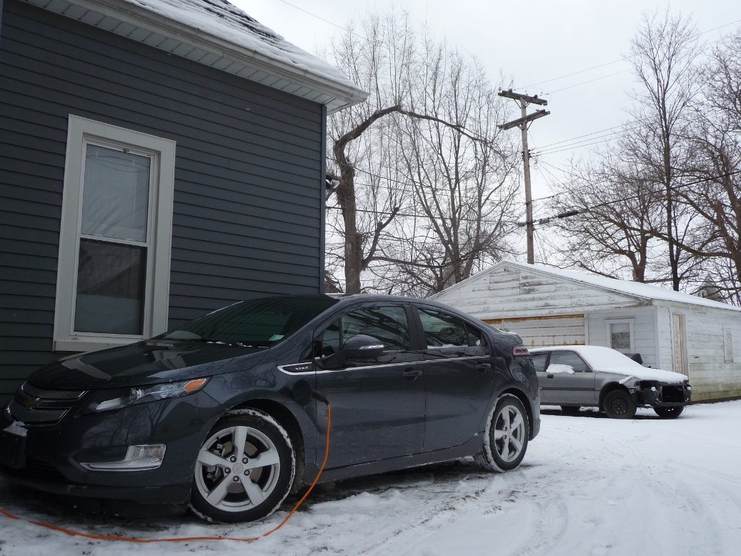
Lucky me, I know electric can be seriously fast.  And this one is ancient compared to the Volt.

For all the bad press, this one is great to drive.  And I partly love it for the battery progress it's driven.

Monday, February 4, 2013

Miscellaneous Projects: Miata Bits

Interspersed in working on my own projects, I also do little side jobs to help out friends. The last couple were little componentry bits for two different Miatas (Miatae?).

#1: Spherical Bearing A-arm Pivots

The first is Allen's '90 Miata with a turbo BP built for the Super Street Modified (SSM) class in SCCA Solo. I've had the privilege of driving this car a few times in various states of tune, and it's really awesome. It's not quite to the extent of the crazy rules in SSM, but it's getting there.


So my job on this one is to swap the rubber bushings in the front lower control arms out for spherical bearings. This is similar to the job done on the GTI rally car in an earlier post, in that it requires welding in a carrier to hold in a spherical bearing that is then retained by a snapring. Allen actually has some polyurethane bushings for these arms, but stiffer bushings have a lot of potential for bind when the pivot axes aren't perfectly co-linear, which means that every time you change the alignment, you effectively alter the wheel rate. Bushings are also still a bit squishier than sphericals, so the benefit is two-fold: increase joint stiffness and reduce suspension bind. That increase in joint stiffness means less camber loss under lateral load and also a reduction in compliance toe change which are both things designed into the suspension to keep people from getting themselves into trouble. However, this car has been re-purposed exclusively to get into trouble so that is all counter-productive.

Allen requested the use of some fancy seals to keep grit out of the sphericals, so he sent me some detailed project requirements:

This is actually some really awesome MS Paint CAD

 I put it in actual CAD because that's how I think:

Really, this is totally redundant though

As with any other project that I write about, I turned the parts out on the lathe:


Here's the finished bearing carrier:


And then I welded them into the arm and stuffed in the spacers that I made to retain the seal and space the joint up to the same width as the factory bushings and reduce the bearing bore to the factory bolt diameter:


Blast, paint, assemble...and there you have some bind-free, high-stiffness A-arm pivots!


#2: Coolant Expansion Tank

The next Miata is Curt's ride, which also started out as a turbocharged SSM car. Curt exploded his transmission at an autocross last summer though, and that was enough to push him down the tried and true drop-a-giant-V8-in-it path. He's got a really in-depth build going on, and it is impeccably documented on his website here.

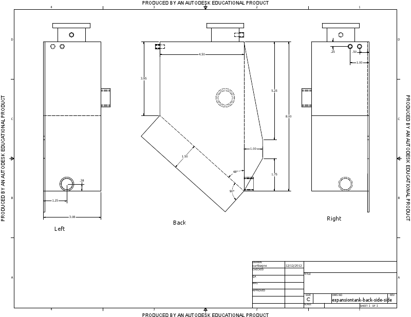
Curt first picked up a welder for this project, and he has come an impressively long way in a short time. But he has no way to weld aluminum, so I offered to fabricate a custom coolant tank for him. The coolant expansion tank is exactly what it sounds like; it's a place where the coolant can expand as it gets hot and it's at the top of the system so it also serves as an air bleed. It's basically a box with some fittings and a cap. This one has a sight glass too as an easy way to check coolant level.

Curt made some nice CAD for me and sent me some drawings:


Again, I built my own CAD model because it helps me think, and I changed a couple dimensions to give me some clearance to weld:


There's not much to this except to cut all the pieces out of aluminum and weld them together. I used the lathe to make a huge fitting to thread the sight glass into, but the rest of it was just taking the fittings that Curt sent me and welding them to a box.


Great practice welding aluminum for me. I could use some more, but the part seems sound. And here it is sitting front and center in his engine bay:


Monday, January 28, 2013

Miscellaneous Projects: Coffee and Side Tables


This isn't remotely car-related, but it's still fabrication...

My fiancée Jackie and I are trying to make our house look less like a hodgepodge of stuff that we got while we were in school, so we're starting to decorate with a specific aesthetic in mind. However, we're still um...frugal people, so we decided to build some tables rather than buying them.

Jackie loves the idea of a thick wooden tabletop with thin metal legs, which she had seen in some expensive designer furniture.


I felt pretty confident that we could do this a little cheaper and with a bit of our own style, so we started by copying a pretty popular concept of using an IKEA Lack tabletop that we already had and building a steel frame for it.

Of course I can't start a project without CAD

We went and bought a bunch of 1/2" square tube:


We cut it up and started welding it together


And it quickly became a great looking side table!


With that great success, we decided to tackle a bigger project to replace our IKEA Lack coffee table. Instead of re-using that tabletop though, we decided to make our own out of solid wood. Conveniently, there were two boards of some nice-looking wood nailed down to my garage rafters to serve as walkways. I took them down when I renovated the garage and left them outside for about a year because I had no place to put them. They ended up being perfect for this project.

I'm not a woodworker at all, so I had no idea what I was doing here, but I needed to join three lengths of board side by side to make the tabletop. Luckily, the look that we're going for doesn't require a perfectly smooth surface, so I didn't bother with jointing or planing the boards. I opted to pocket-screw the top together as it was the easiest and cheapest option.

I drilled a bunch of pocket holes with a super cool Kreg pocket hole jig:


Then I used wood that I had lying around as clamping cauls and screwed the boards together.

My race car is sad that it's being ignored for furniture. And that it's being used as a storage cabinet.

The build of the table's steel frame was pretty much identical to that of the side table, so I won't show any redundant pictures. This is how the final product turned out:


It looks like it's super fragile, but it's sturdy enough to stand on. I wouldn't try jumping or dancing on it though. I think we're going to leave the heat coloration from welding and just spray both table frames with clear.

Monday, December 17, 2012

Project Starlet: Rear Axle Build-Up


 A lot has happened on the Starlet since I introduced it like a year ago, but not really as much as I'd like. During the autocross season, I don't really get much done, so now that that's over, I've been digging into it a little more. I'll get to a major-ish update later, but since I just built up the rear axle, I'll post about that now.

The Starlet comes with a solid axle utilizing a tiny little 6" ring gear and it's held on with a triangulated four-link suspension. This is the same kind of suspension as the "quadra-link" that was used on Mustangs up until the S197 was introduced in 2005. Unfortunately, it is also not-so-affectionately known as "quadrabind" because it demands a lot of deflection from its bushings in both roll and ride motions, so stiffness would increase significantly with suspension travel, causing all kinds of dumb handling problems. The Starlet is no different, except that it's an economy car so nobody cares.

Well, I care. So part of the plan for this car is to basically scrap the rear suspension in favor of a different design. Incidentally, I'm following what Ford did with the Mustang and replacing the four-link with a 3-link and a Panhard bar. While I'm at it, I'm also changing out the dinky little Toyota axle for something that won't explode when subjected to more than the 60 hp that it was designed for.

I ended up deciding on an axle from an '84-'85 Mazda RX-7 GSL-SE for a few reasons: It can handle a decent amount of power, it's not as heavy as common axles like a Ford 8.8, a GM 10-bolt or a Toyota 8", and it's a lot easier to find than an AE86 axle. There are other little factors like the fact that it shares a bolt pattern with the Starlet and comes with a nice clutch-type diff from the factory. That's probably true of the AE86 axle as well, but like I said, the RX-7's are a lot more ubiquitous especially in the midwest.

Check it out; a real ramped clutch-type diff!

I ended up finding a local guy parting out a GSL-SE, so I was able to just drive a few miles, stuff it in the back of my Fit and bring it home for a very reasonable price. It just sorta sat under my bench in the garage for a while, but I just recently took it out and slid it under the car to see what it looks like. It turns out it's waaay too wide, as it's about 5" wider from hub face to hub face, so on top of having to cut off all the brackets and weld on new ones, I also have to narrow the housing and get the axles cut down and re-splined.

So let's get to it. First, I stripped out the diff and axles and ground off all the tabs on the axle housing except for the pair used for mounting the sway bar which I've decided I'll keep for now. This took a long time and turned my garage floor black.


Then, I made all the tabs. Oh, I guess somewhere in here I also designed the suspension. That is surprisingly uninteresting though. Basically, I guessed at target values and saw how close I could get to them in a way that would be somewhat easy to implement. So I picked a super low ride height, decided that I would re-use the lower control arm mounting points and figured out the rest from there.Here are some of the tabs and things. I welded the panhard bar mount together off the axle to make life easier. I also have no confidence in my design, so I put in extra holes to allow for (very) coarse adjustment to things like roll center, anti-squat and roll steer.

These are lower control arm tabs (windowed for lightness!)

This is an adjustable toothy plate for mounting the panhard bar at various heights

After that, I hit the point of no return when I lopped the ends off of the housing. This is scary because they carry the wheel bearings and need to be nicely aligned to the center housing area, so they're not going back on without some work. I was smart enough to measure the angle of the brake mounting bosses first so at least I could get one thing right when I pieced it all back together.

One of my rare thinking-ahead moments

The final disassembly step was to lop off the extra width on the housing. I decided to take 2.25" off of each side based on some crude measurements that I took with the axle under the car. This was done in a crazy looking way by putting the entire axle housing in a bandsaw.

Can you tell that I love my digital angle finder?

That was a little scary, but after measuring 19 times and cutting once, it turned out about right. Meanwhile, I smoothed out the faces of the axle ends/bearing carriers on the lathe so I could weld them cleanly to the axle housing.

It wouldn't be one of my updates without a picture of this lathe

While I was on the lathe, I also made some dummy bearings to clamp into the diff carrier as well as to press into the wheel bearing carriers. These dummy bearings all had a matching hole in the middle through which a big straight solid steel shaft was passed through to ensure alignment.

I saw this great tip somewhere of using a factory scissor jack to level out the housing

After measuring another 100 times, I welded the ends on.


And then I welded on all the suspension tabs.


I made a lot of little plates to box them in too.

  
The panhard mount also needed some little tubes to give it some lateral stiffness since all of the rear axle's lateral load is transmitted into it.

A giant pain both to miter and to weld

And all of a sudden, a finished axle!

Actually, this took a ridiculously long time

I knocked out the alignment rod...and oh wait, the axle is super crooked!

For reference, the yellow end of the rod should be in the middle of that hole...

I was a little alarmed because I don't have the heavy equipment normally used to straighten axle housings. That usually consists of a gigantic I-beam, some big chains, a bottle jack and an oxyacetylene torch. Well, I guess I had a bottle jack in my truck, but those other things are important too. I had also heard of using an OA torch to heat up part of the housing and then quenching it with water to shrink that area and pull the axle straight. I liked this idea, but again, no OA torch. So I instead used the TIG welder torch to strike up an arc on the housing. Wandering the torch around a bit was enough to get a decent chunk of the housing cherry red.


And then a quick quench with a wet rag.

   This is a boring looking photo

A few iterations of this on each side, and I was able to slide the alignment rod in and out by hand. And there you have it, a narrowed and custom tabbed RX-7 axle housing.


I unfortunately can't cut splines on the halfshafts, so those will be sent to Dutchman Motorsports to get shortened. Then, with some work on the chassis end, and some money sunk into decent shocks, I should be able to bolt this thing up and have some rear suspension!