ICEngineering Subjects

Showing posts with label Design and Fabrication. Show all posts

Thursday, June 13, 2013

Project Starlet: Drivetrain-Related Things

 
Somehow, there are only 2 posts about this car even though I feel like I've done a bunch of work to it. It turns out that I've started on a lot of different parts of the car, and since I haven't really done anything to completion, I don't feel ready to report on it. Well, too bad for me; I've done some stuff and if I don't write about it, I'll forget about what it was. On with the story.

Uh...where did I leave off...?

Engine and Transmission

I went through a lot of my trademark waffling when trying to pick a drivetrain for this car. My first thought was to do a 4AGE, since it would be kinda period correct and it's a solid motor, but it's pretty ancient by now. At the other end of the spectrum, it'd be cool to do a small block Chevy because they apparently go with everything. However, an LSx is pretty heavy. I know that's the cliché that people cite when they say that builders are "removing the soul" from some lightweight sports car, and then somebody points out that it's only a 50 lb weight gain over stock or something. Admittedly, those motors are light for what they are, but modern four-cylinder motors are still substantially lighter. In addition, the Chevy V8's need huge transmissions and the giant torque numbers will require something like an 8.8" rear axle (and if you've been following along, you've seen that I've already decided on a dinky little 7" thing).

So with these points considered, I ended up deciding on a Ford Duratec/Mazda MZR inline four cylinder. It's a very light all-aluminum engine with efficient head design and it's ridiculously common. This engine architecture is used in the Ford Focus, Fusion, Escape, Ranger and Transit Connect as well as the Mazda 3, 6, Tribute, B2300, and even the MX-5 Miata (there are probably a few I'm forgetting there too). It also comes in a whole bunch of different variants, ranging from a 2.0L in the Focus and MX-5 up to a 2.5L in later Mazdas. I decided on the 2.3L variant because it seemed like a good size for a turbo motor, and because it's readily available in a RWD configuration from the pickup trucks and those pickup motors don't have balance shafts, so they're a little lighter and more efficient. Uh...so it wasn't super well thought out, but these engines are popular and frequently used in swaps and in motorsport applications...though mostly in Europe. So I bought an engine out of a 17K mile Ranger from a junkyard. I'd put a picture of the acquisition phase here if I was significantly better at documenting what I do, but I'm not so instead here's a picture of me trying to stuff it into the car!


I also needed a transmission, obviously to do transmission-y things, but also so I could determine fitment in the vehicle. For this, the only longitudinal manual transmissions that bolt right up to your average Duratec are the Ranger 5-speed and the MX-5 5-speed and 6-speed. I decided against the Ranger trans because it has truck-y gear ratios, and decided on the MX-5 6-speed because they're apparently a lot sturdier than the 5-speeds. Heavy though. So I got one of those too.

And even took a picture of it and the box that it arrived in on my doorstep

Eventually, I bolted those two things together, and tried positioning it the way I wanted it in the car. Unfortunately, that transmission is gigantic, so I had to do a lot of uh...clearancing to make it fit.

This gets less ugly later. Not much less though

I bought some polyurethane bushings from some off-road shop, machined a couple of billet mounts for the engine and fabricated a steel thingy for the back end of the transmission. Oh, another detail of this particular transmission is that it uses what Mazda calls a "powerplant frame" or PPF, so instead of attaching the transmission to the body, it runs a huge beam down the length of the tunnel to attach it to the diff nose. My RX-8 actually does this too. What that means is that the mounts on the transmission are weird, so the interface I made for it is weird too.

That tunnel brace will have to be a lot beefier. Also, these photos suck

That's cool. I have a different engine firmly bolted into this vehicle now! Somehow, I also did this in the middle of winter with this much space in the garage:

I suppose I could have turned on the lights for this photo op


Oiling

Very quickly, oiling became a serious problem for this particular engine/chassis combination. The first problem is that the Ranger uses a rear-sump oil pan, while the Starlet uses a front sump. That means that the Starlet's front subframe (really just a crossmember in this case) exists in space where the oil pan would like to be. The other issue is that the MX-5 transmission demands that the engine be tilted ten degrees toward the passenger's side of the car, so the oil pan would be crooked anyway. The MX-5 pan would be oriented correctly, but the sump clearance problem is even worse. So those pictures of the engine in the car also show the engine with no oil pan. Clearly a problem.
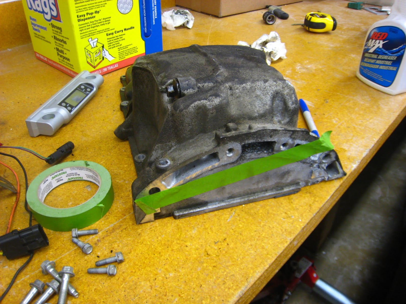
This is the best shot I have of the stock Ranger pan. It's maybe a little ominous

What do you do when nobody makes a pan that will allow you to do the engine swap you want? I don't really know for sure, but my guess is that you cut up the existing pan until it fits and then fix the problem with welding (the way I fix most of my problems). In the photo above, I needed to remove almost everything above that green tape line. Here's a view from the bottom of the car with the pan hacked up to fit:

 Note that you can see into the engine around the middle of the photo

I also had to cut off everything else that was left so I could put a sump up front. I then got to work reconstructing the whole thing.


Incidentally, the oil pickup also had to be relocated from the back to the front, so I left the bottom off the pan so I could see where it was going.


I finished off the bottom of the pan and filled it with water to determine how grossly short of my desired capacity it was. The sump is very small because it's a lot shallower than stock for ground clearance, and the crossmember eats up a lot of the volume I'd like to use. I ended up with something like 3.1 quart capacity, which is less than the 4 quarts that I'd like to see (based on no real science).

Looks nice, but sadly too small

The only option I had at this point to add volume was to add wings to the sides. Wings are a bit of a pain because they make it very difficult to access some of the bolts for attaching the pan to the engine block, so I tried to make sure that I left a decent amount of clearance for fishing bolts in and out. I simply cut some slots the sides of the pan with a plasma cutter (to let oil flow in and out of the wings), bent up some C-shaped things and welded them on.


I also needed a drain plug, and I rather liked the stock arrangement, so I cut that corner off the old sump and welded it on.


A dipstick is a nice thing to have too, and you may notice from two photos above that the dipstick hole in the side of the pan leads to an area that is not inside of the pan itself, so I turned a dipstick bung on the lathe and welded that in...


I then closed up all the holes, checked for leaks and checked capacity again to find that I was just a little over 4 quarts. I'll be running an oil cooler and maybe an Accusump too so I'll have a bit of extra capacity with those. The pan still needs some baffles and a windage tray, so it's not done, but it's at a point where it keeps crap out of the engine and tells me what I need to know about fitment.

Probably the most complicated fabricated aluminum thing I've made to date

On to the next oiling problem! You may or may not have noticed in this picture:


that there is a machined spot with some oily holes in it by the U-joint at the end of the steering column (that thing that looks like a rusty funnel on the right side of the photo). That's where the oil filter take-off used to be. It wants to be right where that steering shaft is, and the filter itself wants to be where the steering rack is. Obviously that won't work either, so a remote-mounted filter is in order. Unfortunately, most filter relocation kits still attach to the existing filter mount, so I would have to make something once again. I also didn't have a whole ton of clearance to the steering system, so it would have to be fairly low-profile. I did some measuring of the stock part, made a CAD model, stuck a chunk of aluminum in the big machine, bought some AN nipples, did some welding and made myself a cool filter take-off. I still need to buy some expensive hoses and a filter mount, but at least I know that the engine fits! Naturally, I have no photos of it installed...


I've done a bit of other stuff too, but this has gotten quite long, so I'll leave it here for now.

Wednesday, March 13, 2013

STX RX-8: Diffs and Dampers

 
As detailed in the last post, I bought a bunch of stuff. Of course, I don't like to make things too easy on myself, so it wasn't as simple as bolting on the Koni 2812's and sticking the OS Giken diff in the rear end. Let's start with the dampers.

The dampers were mostly good to go right out of the box, but I wanted some work to do. The first thing I did was have my friend Allen (who owns the turbo Miata discussed here) run them on a shock dyno along with my old Koni Yellows so that I could baseline them and determine how healthy they were. I got a bunch of cool charts like this:


This was also helpful because it told me that one of the dampers was a little low on gas pressure. For those who don't know, gas charged monotube dampers like the Koni 2812 have a floating piston inside of them that moves up and down to allow the fluid chamber volume to stay constant as the piston rod enters the shock body through the damper's stroke. The floating piston is pushed on by high pressure nitrogen gas so that when the piston rod leaves again, it doesn't induce vacuum in the fluid which would cause air bubbles to precipitate out and make the damping forces really unpredictable. That's all clear? Good.

I could get the whole set rebuilt at some crazy cost, but since I'm cheap and don't like shipping stuff, I decided to just leave the old fluid since it seems to be damping ok and simply refresh the nitrogen gas charge in all the dampers. That sounds pretty simple, except that to keep a low profile on the damper body, Koni's charge port is just a hole with a bolt in it, which unlike a schrader valve has nothing to to thread a fill tool onto and requires a bunch of rotation of a socket head screw to open and close the "valve."

So I went to Harbor Freight, bought some cheap locking pliers and made a tool!

 
It's not that clever, since it's just copied from pictures I found of the actual Koni tool.

That upper part with the valve and knob sticking out of it creates a sealed chamber around the fill screw once it's clamped around the shock body, and then the knob is attached to an allen key sealed to the chamber for opening and closing. The idea is sound, except even with the smallest chamber that I could reasonably make, it still required 30+ pounds of pushing against the gas pressure to get the allen key seated in the screw and was also a little bit finicky about sealing against the shock body. So thanks to Allen for dealing with that for me!

So now the shocks are good as almost-new (which is different from almost good as new). Another annoying thing is that the adjusters for the front dampers are pretty hokey looking for super high end shocks. As far as I can tell, damping adjuster knobs are like the pride and joy of many damper manufacturers. They're usually really pretty machined and brightly anodized things. The Koni adjusters are basically nuts.

They're so tiny, I couldn't even turn them by hand!

Given how lazy I normally am, I probably would have just left them. However, one of them was lost in shipping and Koni wants $12 for these things! Really not so bad, but it was an excuse to make something cool. A little bit of machine time later, I had some nice knurled aluminum knobs that I didn't need tools to operate (picture later).

The last thing is actually something that I had put off from last season. I had installed spherical bearings in the rear shock tops, but that was easy stuff because it only needed very basic manual machine operations and a little bit of welding. The fronts would need new top hats made from scratch, so I actually got through about 1/3 of the fabrication on those and then set it aside for some reason. I decided to pick that back up and finish it. I first tried the lazy approach which was to finish them up with only a lathe operation.


But it turns out that shock tops are shaped like almost-triangles for a reason, and the reason is that circles don't fit. So I fired up the big machine and made them nice looking.


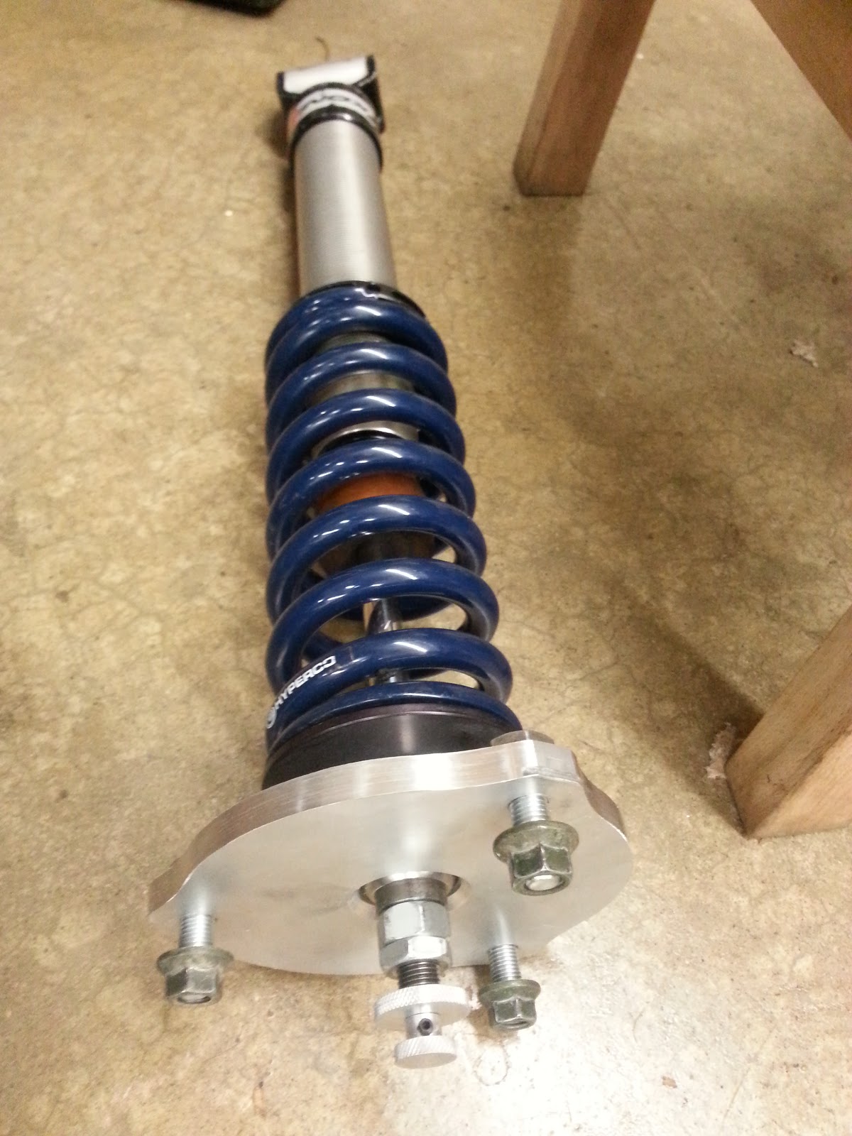
With those all done plus the fancy new adjusters, I assembled everything together for a nice photo.


Now on to the diff. This was pretty much just a bunch of wrenching. Step 1 was to take apart everything out back.


I actually disassembled more than you'd need to for just the diff, but I also wanted to change out my wheel studs, which for some stupid reason requires dismantling the rear upright and ruining a perfectly good set of wheel bearings. So Rob and I spent a couple of quality hours with a press doing that...

 This is what happens when you try to remove the hub. The bearing is wrecked.
 But it's nice enough to leave the race stuck on the hub...
 Which needs to be carefully ground off
 Just so I can put in some studs
 Installation is the reverse of removal... 

With that taken care of, we pulled out the diff and swapped it for the OS Giken unit. I really really didn't want to mess with setting lash because the RX-8 uses swappable shims to set both lash and bearing preload, and I didn't want to buy any, so I was just hoping that the carrier-bearing-to-ring-gear-mounting-distance would be exactly the same as stock...

OS Giken on the left, stock Torsen on the right. Height gauge in the back.

Turns out it was! So that was easy enough. We checked the lash just in case, but it of course required no adjustment.


A few hours in the garage later, and we got the rear end all buttoned up again.

That's Rob. People have trouble telling us apart because we're both Chinese.


Now it pretty much just needs an alignment and a wash, and it'll be ready to go a Test-n-Tune in April.

Monday, February 4, 2013

Miscellaneous Projects: Miata Bits

Interspersed in working on my own projects, I also do little side jobs to help out friends. The last couple were little componentry bits for two different Miatas (Miatae?).

#1: Spherical Bearing A-arm Pivots

The first is Allen's '90 Miata with a turbo BP built for the Super Street Modified (SSM) class in SCCA Solo. I've had the privilege of driving this car a few times in various states of tune, and it's really awesome. It's not quite to the extent of the crazy rules in SSM, but it's getting there.


So my job on this one is to swap the rubber bushings in the front lower control arms out for spherical bearings. This is similar to the job done on the GTI rally car in an earlier post, in that it requires welding in a carrier to hold in a spherical bearing that is then retained by a snapring. Allen actually has some polyurethane bushings for these arms, but stiffer bushings have a lot of potential for bind when the pivot axes aren't perfectly co-linear, which means that every time you change the alignment, you effectively alter the wheel rate. Bushings are also still a bit squishier than sphericals, so the benefit is two-fold: increase joint stiffness and reduce suspension bind. That increase in joint stiffness means less camber loss under lateral load and also a reduction in compliance toe change which are both things designed into the suspension to keep people from getting themselves into trouble. However, this car has been re-purposed exclusively to get into trouble so that is all counter-productive.

Allen requested the use of some fancy seals to keep grit out of the sphericals, so he sent me some detailed project requirements:

This is actually some really awesome MS Paint CAD

 I put it in actual CAD because that's how I think:

Really, this is totally redundant though

As with any other project that I write about, I turned the parts out on the lathe:


Here's the finished bearing carrier:


And then I welded them into the arm and stuffed in the spacers that I made to retain the seal and space the joint up to the same width as the factory bushings and reduce the bearing bore to the factory bolt diameter:


Blast, paint, assemble...and there you have some bind-free, high-stiffness A-arm pivots!


#2: Coolant Expansion Tank

The next Miata is Curt's ride, which also started out as a turbocharged SSM car. Curt exploded his transmission at an autocross last summer though, and that was enough to push him down the tried and true drop-a-giant-V8-in-it path. He's got a really in-depth build going on, and it is impeccably documented on his website here.

Curt first picked up a welder for this project, and he has come an impressively long way in a short time. But he has no way to weld aluminum, so I offered to fabricate a custom coolant tank for him. The coolant expansion tank is exactly what it sounds like; it's a place where the coolant can expand as it gets hot and it's at the top of the system so it also serves as an air bleed. It's basically a box with some fittings and a cap. This one has a sight glass too as an easy way to check coolant level.

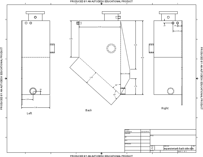
Curt made some nice CAD for me and sent me some drawings:


Again, I built my own CAD model because it helps me think, and I changed a couple dimensions to give me some clearance to weld:


There's not much to this except to cut all the pieces out of aluminum and weld them together. I used the lathe to make a huge fitting to thread the sight glass into, but the rest of it was just taking the fittings that Curt sent me and welding them to a box.


Great practice welding aluminum for me. I could use some more, but the part seems sound. And here it is sitting front and center in his engine bay: